Open-source necromancy - rebuilding forgotten Arduino-like board
July 27, 2018
History
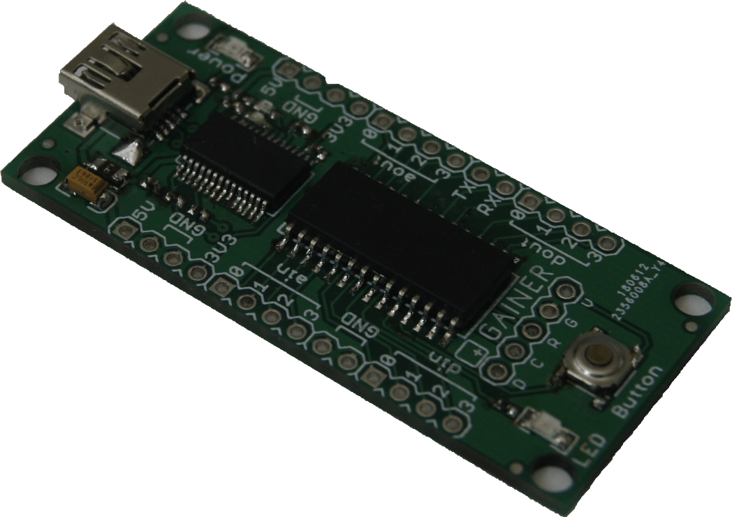
GAINER is an reconfigurable I/O module. It uses Cypress ~(C) PSoC 1 microcontroller with mixed signal array that has configurable analog and digital blocks. Launched in 2006 in Institute of Advanced Media Arts and Sciences in Japan it gave birth to a new open-source (and open-hardware) educational board that has extraordinary features including programmable gain amplifier for analog inputs, reconfigurable amount of analog or digital I/O, capacitive sensing and other nice things - all controlled by simple serial interface using Processing or other software like Max/MSP. In compaction Arduino didn’t have these features - especially in analog side. But Arduino has one advantage - it could work itself after programming and GAINER cannot. Project was active to about 2009 and it’s site died this year. Like one of many interesting projects, it was abandoned and forgotten, but because of the open-source it still can be restored! Everyone can just grab the files make their own GAINER, maybe tweak the code and just have fun with it - and this is what will be this post about.
Step one: Grab the files and sources
Fortunately Wayback Machine saved multiple snapshots of the project site, and SouceForge repository containing hardware, firmware and it’s sources, plugins for Processing, Max/MSP and Flash is still working, so there will be no problem with that.
Step two: Build and program GAINER
First thing that will be necessary is the PCB. There are EAGLE files with the schematic and PCB design in SourceForge repository, but the board uses old USB port and is relatively big. Fortunately, SparkFun has made their own redesigned PCB with mini USB port and they still share the PCB and schematic for their version too. So everything to do was just make PCB in home or create gerber files and send them to any company that makes PCBs. The second option was better for me, because I wanted a nice silkscreen, soldermask and good precision of pads and traces.
What about the components? GAINER uses just 2 ICs - PSoC processor and USB-UART bridge. Resistors, USB socket, some LEDs and capacitors will be no problem - there is many old broken devices like laptop motherboards that have these elements.
The USB-UART bridge IC, FTDI FT232RL is relatively cheap and available everywhere, but the Cypress CY8C29466-24SXI PSoC1 μC is now a relatively rare component, but I still managed to find one in my country online shop for ~9$. This microcontroller is heart of GAINER board ans it’s probably the most interesting μC I know. It’s 8-bit microcontroller with proprietary M8C core that is somewhat similar to Intel 8051 but has maximum two (!) general-purpose registers and no open-source C compiler (and only 2 commercial compilers from ImageCraft and HI-TECH). Developing for this core is a nightmare because of that. On the other hand, it’s called Programmable System-on-Chip for a reason - it’s a microcontroller with reconfigurable digital and analog systems that behaves like simpler and more powerful CPLDs in single chip. Really impressive.
It was time to solder them to board. Unfortunately, some SMD elements were in 0402 size (one of the smallest SMD size!), so soldering with only soldering iron was hard, but possible. After some testing with methods for soldering main ICs it was time to assemble the whole board. Soldering process took about 1 hour but I think it was worth it. Testing for any short circuits using multimeter went fine, so the only thing that had to be done was programming the PSoC chip.

But how to program PSoC1 Chip without programmer?
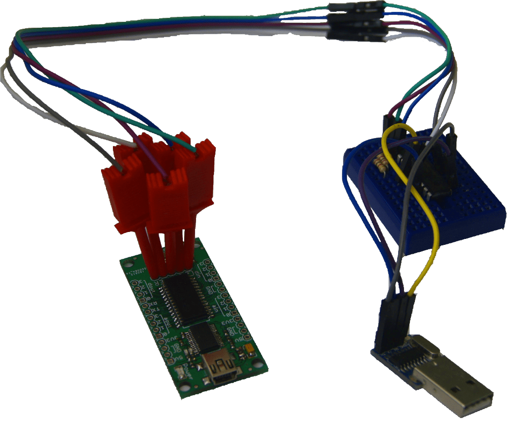
The answer is simple - just make one. Werner Almesberger in 2006 actually made a bunch of open-source tools for the M8C Cypress chips - an assembler, disassembler, simulator and programmer software for various types of hardware programmers (Parallel port for example) and all software is still available via SoureForge site and a GitHub repository, witch has a modified Makefile for build compatibility with any modern GNU/Linux environment. The hardware site is available in SourceForge containing designs for various programmers. I decided to build waspic only because it can be easily used with any USB-UART bridge. The firmware for it was written using PIC assembly for PIC16F88 chip and building a hex file for it required ancient version of gpasm so I share the hex file here. Programming one of the most popular PICs shouldn’t be a problem (but again - I do not have any PIC programmer, so I asked a guy selling those chips to program it with hex file)
To be honest, there was a simpler way to program PSoC1 chips by using Arduino with arduino-hssp made by Dirk Petrautzki witch is an Arduino port of AN44168 HSSP Protocol Implementation from Cypress. It works like a charm with most of PSoC1 family (at least with CY7C27443), but there is a little problem - CY8C29466 is a multi-bank device (it has to switch ROM banks to use all 32kB - it’s hell for a compiler and any programmer) and arduino-hssp don’t support those devices - there is only a comment in code:
setAddress(0, (here)); // TODO support for multiple banks

With working programmer on a breadboard there shouldn’t be any problem with programming. The only way to test it is to run:
./m8cprog -5 -w -p /dev/ttyUSB0 CY8C29466 ../../gainer_firmware_v1-1-0rc5/gainer.hex
After solid 40 seconds programmer was done! It was time to test the GAINER board.
Part three: Test it!
GAINER uses serial protocol to communicate with computer. Command list is explained in these tables (witch were found in gainer firmware source code zip):
Initialize
If you want to use in a configuration, send reboot command anyway, then enter the configuration.
| Command | Response | Comment |
|---|---|---|
| Q* | Q* | exit to configuration 0 |
| KONFIGURATION_n* | KONFIGURATION_n* | n: configuration (1-8) |
Configurations
| Configuration | Analog inputs | Digital inputs | Analog outputs | Digital outputs | Comments |
|---|---|---|---|---|---|
| 0 | 0 | 0 | 0 | 0 | initial configuration just after rebooting |
| 1 | 4 | 4 | 4 | 4 | default configuration |
| 2 | 8 | 0 | 4 | 4 | — |
| 3 | 4 | 4 | 8 | 0 | — |
| 4 | 8 | 0 | 8 | 0 | — |
| 5 | 0 | 16 | 0 | 0 | — |
| 6 | 0 | 0 | 0 | 16 | — |
| 7 | 0 | 8 | 8 | 0 | matrix LED control mode |
| 8 | 0 | 8 | 0 | 8 | capacitive sensing switch mode (first 4 ports only) |
Command list
All values are in hex and should be in upper case (e.g. 0A, F8…)
| Command | Response | Comment | Works in configurations |
|---|---|---|---|
| Set config | |||
| KONFIGURATION_n* | KONFIGURATION_n* | n: configuration (1-8) | 0 |
| I/O | |||
| Dxxxx* | Dxxxx* | set all digital outputs, xx: value | 1, 2, 6, 8 |
| Hn* | Hn* | set specified digital output high, n: port number | 1, 2, 6 |
| Ln* | Ln* | set specified digital output low, n: port number | 1, 2, 6 |
| R* | Rxxxx* | get all digital inputs, xx: value | 1, 3, 5, 8 |
| r* | rxxxxrxxxx… | get all digital inputs (continuous mode), xx: value | 1, 3, 5, 8 |
| E* | E* | exit continuous mode | 1, 3, 5, 8 |
| Tx* | Tx* | set sensitivity for capacitive sensing inputs | 8 |
| Axx…xx* | A* | set all analog outputs, xx: value | 1, 2, 3, 4 |
| anxx* | anxx* | set specified analog output, n: port number, xx: value (00~FF, 8bit) | 1, 2, 3, 4 |
| anx…x* | a* | set specified analog output, n: row number, x: value (0~F, 4bit) | 7 |
| I* | Ixxxx* | get all analog inputs, xx: value | 1, 2, 3, 4 |
| i* | ixxxxixxxx… | get all analog inputs (continuous mode), xx: value | 1, 2, 3, 4 |
| Sx* | Sxx* | get specified analog input (continuous mode), xx: value | 1, 2, 3, 4 |
| Mx* | Mx* | ain sampling mode, x:mode (0: scan all channles, 1: scan ain 0/4 only) | 1, 2, 3, 4 |
| Button/LED | |||
| (button pressed) | N* | the on-board button is pressed (no need to send a get command) | 1, 2, 3, 4 |
| (button released) | F* | the on-board button is released (no need to send a get command) | 1, 2, 3, 4 |
| h* | h* | turn the on-board LED on | 1, 2, 3, 4 |
| l* | l* | turn the on-board LED off | 1, 2, 3, 4 |
| PGA | |||
| Gxy* | Gxy* | set PGA gain and PGA reference, x: gain, y: reference | 1, 2, 3, 4 |
| Misc | |||
| Q* | Q* | reboot | 1, 2, 3, 4, 5, 6, 7, 8 |
| Vx* | Vx* | verbose mode, x: mode (0: disabled, 1: enabled) | 0 |
| ?* | ?1.0.0.xx* | version number, xx: build number | 0 |
The easiest way to test the board is to
minicom -p /dev/ttyUSB0 -b 38400
and type initialization commands:
Q*
KONFIGURATION_1*
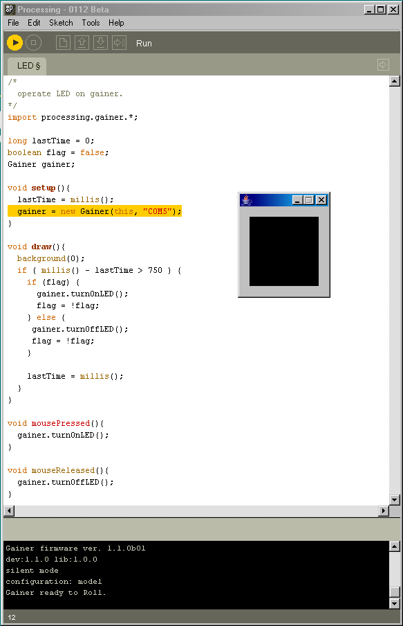
This test went fine, so the chip was programmed properly and USB-UART bridge works! But there is more to test than only initialization. To test other functions I wanted to use GAINER library for Processing found in repository. Unfortunately it uses ancient version of this program and even with the oldest binary of Processing I found GAINER library didn’t work. Only thing I could do is to grab really old version of Processing from GitHub repository and build it. Messing with JDK 1.3 in GNU/Linux environment would be hell, so I used Windows XP VM and Cygwin. With this version the Library worked perfectly.

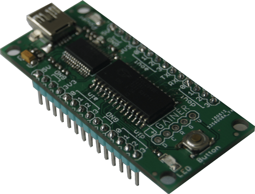
I tested some examples that used analog inputs and everything works. Only thing left to do was to solder goldpins.

Final thoughts
Building GAINER board was really exiting. Discovering all these things about this project and PSoC1 microcontrollers was like time travel for me - old, mostly dead sites and some snapshots from Web Archive were enough to rebuild this project. I learned something about gerber files, soldering 0402 SMD components and building old software from source. It was truly amazing experience and I’m sure there are more abandoned open-source projects witch deserve at least reminding of their existence.